I’m Tiffany Wu, and this is my fourth week at the University of Houston working on my project about ellipsometry under the guidance of my mentor, Professor Baldelli. This week, I collected more data using the proper calibrations, built a replacement part for the machine, and worked on the quarter wave plate mechanism that I built the code for last week.
On Monday, I was reading over the manual for the ellipsometer to learn how to properly calibrate and align the laser of the ellipsometer for proper measurement. Although what I had been doing before yielded a graph that was very similar to the one we wanted, the data was not quite accurate. So, after spending some time trying to figure out all the parts that the manual was referring to, I finally got the sample aligned with the laser. Using the proper alignment method, I recollected the data for the silicon oxide wafer and collected data for a plain gold wafer and sent it to Professor Baldelli. For the remainder of the day, I worked on my presentation for the group meeting on Friday where I would have to present my project and everything I have been working on so far to Professor Baldelli and the other undergraduate and graduate students of his lab.
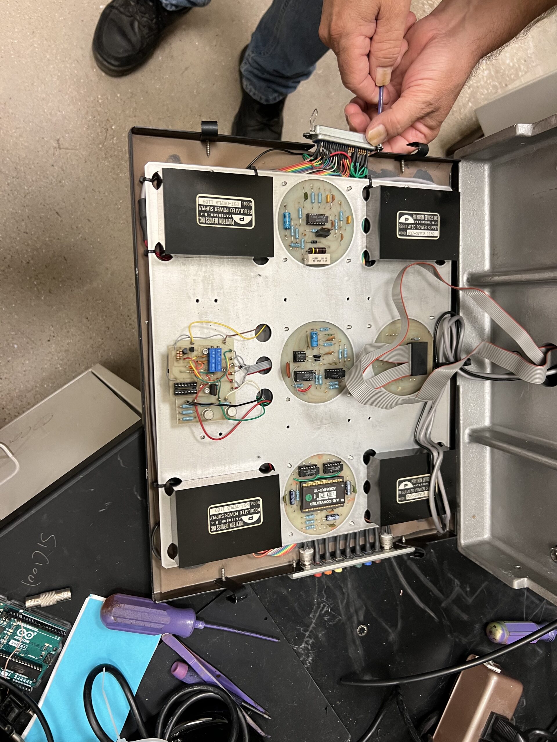
On Tuesday, I was trying to fix a minor issue with the voltage that is sent out from the ellipsometer. For the silicon wafer, when the sine graph would drop to its minimum, the sensitivity of the detector was not high enough to display a small enough voltage, the value would be displayed as just zero on the graph, which needed to be fixed in order to form a smooth graph that could be properly fitted to our model data. There was a tiny dial on one of the sides of the machine that could in theory be turned to adjust the voltage output and shift our graph up and avoid the minimum being at 0, but while trying to turn it, I accidentally unscrewed the whole dial off its placement and it ended up inside the machine and couldn’t be pulled back out. Thankfully, Professor Baldelli helped me to unscrew the bottom covering from the machine and successfully pushed the screw back into its place. Since the machine was already uncovered, we decided to take advantage of the unforeseen situation and trace the wires to the pin that we needed to connect the quarter wave plate output to. Since it is much more difficult to see the layout of the wiring once the cover was on, it was an important step for powering the compensator (quarter wave plate).
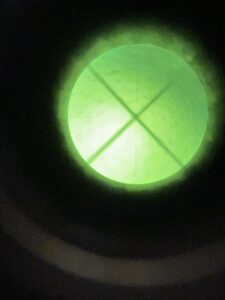
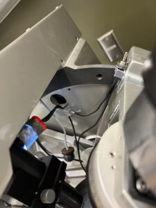
Unfortunately, when I got to the lab on Wednesday, the eyepiece for the alignment of the sample was not working and I could not see any of the lines I was supposed to to make the proper adjustments. After opening the top of the ellipsometer, we determined that the lightbulb that allows us to see the microscopic lines was dead and we needed to find a replacement for a light source. Because the ellipsometer that I’m using is so old, the lightbulb that I needed could not be easily obtained. The machine needed an AC power, but the lightbulbs we had were all LEDs with a DC. Professor Baldelli decided that it would just be easier to build a new light source and direct to the spot we needed. Using the LEDs from a flashlight, a switch, and a 5V DC power supply, I spent the day building the circuit to power the LED. My first attempt sadly failed as I burned out the wires after accidentally letting the positive and negatives touch while the power supply was plugged in. Luckily, I found another 5V power supply to use for my circuit and I very carefully soldered the wires and components together to for my “lightbulb”. I taped the LED to the tube on the ellipsometer that needed the light aimed at, and the problem with the calibration was fixed.
On Thursday, I was comparing the data I got from my samples, and trying to figure out how to fit the graphs to the model equations of ellipsometry. Due to my lack of knowledge on the specifics of the equations and my limited knowledge in that kind of advanced math, it was not very successful. I ultimately spent the rest of my time finishing up my slides for my presentation with Saida and Katya on Friday.
Friday morning was rather hectic, and the three of us woke up very early to buy breakfast for us and the rest of the group members. We arrived to the lab with enough time to rehearse and prepare for our presentation, which was very nerve racking for me since I had never presented any kind of research before. But, thankfully, my presentation went very well, and besides a few minor details that needed to be added, Professor Baldelli was pretty satisfied with the content I had presented. For the remainder of Friday, I was testing my compensator code with the toggle-able voltage output and connecting it to a relay to see if the Arduino could output a high enough voltage to power the relay. From what we tested, having only one pin outputting was not producing enough current to open and close the connection, so I researched ways to increase the current with multiple output pins.
On Saturday, I added the new lines of code that would add another pin to give off a voltage output, and connected the board, power supply, and ellipsometer accordingly. After connecting the wires to what I thought was the correct orientation, we realized that the pins we were checking for continuity were not the right ones. We checked all the different combinations of the pins on the relay, and found the right ones we needed. The wires were properly connected and the relay could successfully be powered on and off. Sadly, the compensator was not moving despite having the proper connections, and so it is yet another problem that I need to troubleshoot.
Next week I am really hoping I can get the compensator to work the way we want it to, and possibly find a way to fit the data to the model. However, next week I have a poster session to prepare for, where I will get to present my work to other professors and parents of the other students doing research, so it is unlikely that I will be able to work much on the ellipsometer.


There are no comments published yet.